

- Arduplane parameters
- LOG_BITMASK: Log bitmask
- Battery monitor settings
- Connecting a gps/compass module
- Custom settings & webinterface
- API
- Default uart order
- Driver specific threads
- Dshot capability
- Ek2_ parameters
- EK2_MAG_CAL: Magnetometer default fusion mode
- Firmware
- Full parameter list of plane latest v4.3.0dev
- ArduPlane Parameters
- LOG_BITMASK: Log bitmask
- AFS_ Parameters
- ARSPD Parameters
- BTN_ Parameters
- CAM_ Parameters
- COMPASS_ Parameters
- CUST_ROT1_ Parameters
- CUST_ROT2_ Parameters
- EK2_ Parameters
- EK2_MAG_CAL: Magnetometer default fusion mode
- EK3_ Parameters
- INS_ Parameters
- INS_HNTC2_ Parameters
- INS_HNTCH_ Parameters
- MNT Parameters
- NTF_ Parameters
- Q_ Parameters
- Q_OPTIONS: quadplane options
- Q_TAILSIT_ Parameters
- RNGFND1_ Parameters
- RNGFND2_ Parameters
- RNGFND3_ Parameters
- RNGFND4_ Parameters
- RNGFND5_ Parameters
- RNGFND6_ Parameters
- RNGFND7_ Parameters
- RNGFND8_ Parameters
- RNGFND9_ Parameters
- RNGFNDA_ Parameters
- SERIAL Parameters
- TECS_ Parameters
- Hal specific threads
- Lockless data structures
- Platform specific threads and tasks
- Q_ parameters
- Q_OPTIONS: quadplane options
- Q_options: quadplane options
- Rc input
- Semaphores
- Specifications
- The ap_scheduler system
- The px4 orb
- The timer callbacks
- Understanding ardupilot threading
- Understanding the example sketch code
Arduplane parameters
LOG_BITMASK: Log bitmask
Note: This parameter is for advanced users
Bitmap of what on-board log types to enable. This value is made up of the sum of each of the log types you want to be saved. It is usually best just to enable all log types by setting this to 65535. The individual bits are ATTITUDE_FAST=1, ATTITUDE_MEDIUM=2, GPS=4, PerformanceMonitoring=8, ControlTuning=16, NavigationTuning=32, Mode=64, IMU=128, Commands=256, Battery=512, Compass=1024, TECS=2048, Camera=4096, RCandServo=8192, Sonar=16384, Arming=32768, FullLogs=65535
Battery monitor settings
These should already be set by default. However, if lost or changed:
Enable Battery monitor with these parameter settings :
:ref:`BATT_MONITOR<BATT_MONITOR>` =4
Then reboot.
:ref:`BATT_VOLT_PIN<BATT_VOLT_PIN>` 10
:ref:`BATT_CURR_PIN<BATT_CURR_PIN>` 11
:ref:`BATT_VOLT_MULT<BATT_VOLT_MULT>` 11.0
:ref:`BATT_AMP_PERVLT<BATT_AMP_PERVLT>` 40.0
:ref:`BATT2_VOLT_PIN<BATT2_VOLT_PIN>` 18
:ref:`BATT2_CURR_PIN<BATT2_CURR_PIN>` 7
:ref:`BATT2_VOLT_MULT<BATT2_VOLT_MULT>` 11.0
Connecting a gps/compass module
This board does not include a GPS or compass so an :ref:`external GPS/compass <common-positioning-landing-page>` should be connected in order for autonomous modes to function.
If the GPS is attached to UART2 TX/RX and powered from the adjacent 4.5V pins, it will be powered when connected via USB, as would the RX if powered from the adjacent 4.5V pins to UART6.
A battery must be plugged in for power to be provided to the pins marked 5V on the board.
Custom settings & webinterface
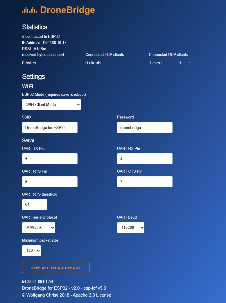
API
DroneBridge for ESP32 offers a REST:API that allows you to read and
write configuration options. You are not limited to the options
presented by the Webinterface (e.g. baud rates). You can use the API to
set custom baud rates or to integrate the system into your own setup.
To request the settings
To request stats
Trigger a reboot
Trigger a settings change: Send a valid JSON
{"wifi_ssid":"DroneBridge ESP32","wifi_pass":"dronebridge","ap_channel":6,"tx_pin":17,"rx_pin":16,"telem_proto":4,"baud":115200,"msp_ltm_port":0,"ltm_pp":2,"trans_pack_size":64,"ap_ip":"192.168.2.1"}to
Default uart order
Serial port protocols (Telem, GPS, etc.) can be adjusted to personal preferences.
Driver specific threads
It is also possible to create driver specific threads, to support
asynchronous processing in a manner specific to one driver. Currently
you can only create driver specific threads in a manner that is platform
dependent, so this is only appropriate if your driver is intended to run
only on one type of autopilot board. If you want it to run on multiple
AP_HAL targets then you have two choices:
- you can use the register_io_process() and
register_timer_process() scheduler calls to use the existing timer
or IO threads - you can add a new HAL interface that provides a generic way to create
threads on multiple AP_HAL targets (please contribute patches back)
An example of a driver specific thread is the ToneAlarm thread in the
Linux port. See AP_HAL_Linux/ToneAlarmDriver.cpp
Dshot capability
All motor/servo outputs are Dshot and PWM capable. However, mixing Dshot and normal PWM operation for outputs is restricted into groups, ie. enabling Dshot for an output in a group requires that ALL outputs in that group be configured and used as Dshot, rather than PWM outputs.
Ek2_ parameters
EK2_MAG_CAL: Magnetometer default fusion mode
Note: This parameter is for advanced users
This determines when the filter will use the 3-axis magnetometer fusion model that estimates both earth and body fixed magnetic field states, when it will use a simpler magnetic heading fusion model that does not use magnetic field states and when it will use an alternative method of yaw determination to the magnetometer. The 3-axis magnetometer fusion is only suitable for use when the external magnetic field environment is stable. EK2_MAG_CAL = 0 uses heading fusion on ground, 3-axis fusion in-flight, and is the default setting for Plane users. EK2_MAG_CAL = 1 uses 3-axis fusion only when manoeuvring. EK2_MAG_CAL = 2 uses heading fusion at all times, is recommended if the external magnetic field is varying and is the default for rovers. EK2_MAG_CAL = 3 uses heading fusion on the ground and 3-axis fusion after the first in-air field and yaw reset has completed, and is the default for copters. EK2_MAG_CAL = 4 uses 3-axis fusion at all times. NOTE: The fusion mode can be forced to 2 for specific EKF cores using the EK2_MAG_MASK parameter. NOTE: limited operation without a magnetometer or any other yaw sensor is possible by setting all COMPASS_USE, COMPASS_USE2, COMPASS_USE3, etc parameters to 0 with COMPASS_ENABLE set to 1. If this is done, the EK2_GSF_RUN and EK2_GSF_USE masks must be set to the same as EK2_IMU_MASK.
Firmware
Firmware for these boards can be found here in sub-folders labeled
“MatekH743”.
Firmware that supports :ref:`bi-directional Dshot <bidir-dshot>` is labeled “MatekH743-bdshot”.
[copywiki destination=”plane,copter,rover,blimp”]
Full parameter list of plane latest v4.3.0dev
You can change and check the parameters for another version:
This is a complete list of the parameters which can be set (e.g. via the MAVLink protocol) to control vehicle behaviour. They are stored in persistent storage on the vehicle.
This list is automatically generated from the latest ardupilot source code, and so may contain parameters which are not yet in the stable released versions of the code.
ArduPlane Parameters
LOG_BITMASK: Log bitmask
Note: This parameter is for advanced users
Bitmap of what on-board log types to enable. This value is made up of the sum of each of the log types you want to be saved. It is usually best just to enable all log types by setting this to 65535. The individual bits are ATTITUDE_FAST=1, ATTITUDE_MEDIUM=2, GPS=4, PerformanceMonitoring=8, ControlTuning=16, NavigationTuning=32, Mode=64, IMU=128, Commands=256, Battery=512, Compass=1024, TECS=2048, Camera=4096, RCandServo=8192, Sonar=16384, Arming=32768, FullLogs=65535
AFS_ Parameters
ARSPD Parameters
BTN_ Parameters
CAM_ Parameters
COMPASS_ Parameters
CUST_ROT1_ Parameters
CUST_ROT2_ Parameters
EK2_ Parameters
EK2_MAG_CAL: Magnetometer default fusion mode
Note: This parameter is for advanced users
This determines when the filter will use the 3-axis magnetometer fusion model that estimates both earth and body fixed magnetic field states, when it will use a simpler magnetic heading fusion model that does not use magnetic field states and when it will use an alternative method of yaw determination to the magnetometer. The 3-axis magnetometer fusion is only suitable for use when the external magnetic field environment is stable. EK2_MAG_CAL = 0 uses heading fusion on ground, 3-axis fusion in-flight, and is the default setting for Plane users. EK2_MAG_CAL = 1 uses 3-axis fusion only when manoeuvring. EK2_MAG_CAL = 2 uses heading fusion at all times, is recommended if the external magnetic field is varying and is the default for rovers. EK2_MAG_CAL = 3 uses heading fusion on the ground and 3-axis fusion after the first in-air field and yaw reset has completed, and is the default for copters. EK2_MAG_CAL = 4 uses 3-axis fusion at all times. NOTE: The fusion mode can be forced to 2 for specific EKF cores using the EK2_MAG_MASK parameter. NOTE: limited operation without a magnetometer or any other yaw sensor is possible by setting all COMPASS_USE, COMPASS_USE2, COMPASS_USE3, etc parameters to 0 with COMPASS_ENABLE set to 1. If this is done, the EK2_GSF_RUN and EK2_GSF_USE masks must be set to the same as EK2_IMU_MASK.
EK3_ Parameters
INS_ Parameters
INS_HNTC2_ Parameters
INS_HNTCH_ Parameters
MNT Parameters
NTF_ Parameters
Q_ Parameters
Q_OPTIONS: quadplane options
Level Transition:Keep wings within LEVEL_ROLL_LIMIT and only use forward motor(s) for climb during transition, Allow FW Takeoff: If bit is not set then NAV_TAKEOFF command on quadplanes will instead perform a NAV_VTOL takeoff, Allow FW Land:If bit is not set then NAV_LAND command on quadplanes will instead perform a NAV_VTOL_LAND, Vtol Takeoff Frame: command NAV_VTOL_TAKEOFF altitude is as set by the command’s reference frame rather than a delta above current location, Use FW Approach:Use a fixed wing approach for VTOL landings, USE QRTL:instead of QLAND for rc failsafe when in VTOL modes, Use Governor:Use ICE Idle Governor in MANUAL for forward motor, Force Qassist: on always,Mtrs_Only_Qassist: in tailsitters only, uses VTOL motors and not flying surfaces for QASSIST, Airmode_On_Arm:Airmode enabled when arming by aux switch, Disarmed Yaw Tilt:Enable motor tilt for yaw when disarmed, Delay Spoolup:Delay VTOL spoolup for 2 seconds after arming, ThrLandControl: enable throttle stick control of landing rate, DisableApproach: Disable use of approach and airbrake stages in VTOL landing, EnableLandResposition: enable pilot controlled repositioning in AUTO land. Descent will pause while repositioning. ARMVTOL: Arm only in VTOL or AUTO modes. CompleteTransition: to fixed wing if Q_TRANS_FAIL timer times out instead of QLAND. Force RTL mode: forces RTL mode on rc failsafe in VTOL modes overriding bit 5(USE_QRTL).
Q_TAILSIT_ Parameters
RNGFND1_ Parameters
RNGFND2_ Parameters
RNGFND3_ Parameters
RNGFND4_ Parameters
RNGFND5_ Parameters
RNGFND6_ Parameters
RNGFND7_ Parameters
RNGFND8_ Parameters
RNGFND9_ Parameters
RNGFNDA_ Parameters
SERIAL Parameters
TECS_ Parameters
Hal specific threads
On platforms that support real threads the AP_HAL for that platform
will create a number of threads to support basic operations. For
example, on Pixhawk the following HAL specific threads are created:
- The UART thread, for reading and writing UARTs (and USB)
- The timer thread, which supports the 1kHz timer functionality
described above - The IO thread, which supports writing to the microSD card, EEPROM and
FRAM
Have a look in Scheduler.cpp inside each AP_HAL implementation to see
what threads are created and what the realtime priority of each thread
is.
If you have a Pixhawk then you should also now setup a debug console
cable and attach it to the nsh console (the serial5 port). Connect at
57600. When you have connected, try the “ps” command and you will get
something like this:
Lockless data structures
The ArduPilot code also contains examples of using lockless data
structures to avoid the need for a semaphore. This can be a lot more
efficient than semaphores.
Two examples of lockless data structures in ArduPilot are:
- the _shared_data structure in
libraries/AP_InertialSensor/AP_InertialSensor_MPU9250.cpp - the ring buffers used in numerous places. A good example is
libraries/DataFlash/DataFlash_File.cpp
Go and have a look at these two examples, and prove to yourself that
they are safe for concurrent access. For DataFlash_File look at the use
of the _writebuf_head and _writebuf_tail variables.
It would be nice to create a generic ring buffer class which could be
used instead of the separate ringbuffer implementations in several
places in ArduPilot. If you want to contribute that then please do a
pull request!
Platform specific threads and tasks
On some platforms there will be a number of base tasks and threads that
will be created by the startup process. These are very platform specific
so for the sake of this tutorial I will concentrate on the tasks used on
PX4 based boards.
In the “ps” output above we saw a number of tasks and threads that were
not started by the AP_HAL_PX4 Scheduler code. Specifically they are:
The startup of all of these tasks is controlled by the PX4 specific
rc.APM script.
That script is run when the PX4 boots, and is responsible for detecting
what sort of PX4 board we are using then loading the right tasks and
drivers for that board. It is a “nsh” script, which is similar to a
bourne shell script (though nsh is much more primitive).
Q_ parameters
Q_OPTIONS: quadplane options
Level Transition:Keep wings within LEVEL_ROLL_LIMIT and only use forward motor(s) for climb during transition, Allow FW Takeoff: If bit is not set then NAV_TAKEOFF command on quadplanes will instead perform a NAV_VTOL takeoff, Allow FW Land:If bit is not set then NAV_LAND command on quadplanes will instead perform a NAV_VTOL_LAND, Vtol Takeoff Frame: command NAV_VTOL_TAKEOFF altitude is as set by the command’s reference frame rather than a delta above current location, Use FW Approach:Use a fixed wing approach for VTOL landings, USE QRTL:instead of QLAND for rc failsafe when in VTOL modes, Use Governor:Use ICE Idle Governor in MANUAL for forward motor, Force Qassist: on always,Mtrs_Only_Qassist: in tailsitters only, uses VTOL motors and not flying surfaces for QASSIST, Airmode_On_Arm:Airmode enabled when arming by aux switch, Disarmed Yaw Tilt:Enable motor tilt for yaw when disarmed, Delay Spoolup:Delay VTOL spoolup for 2 seconds after arming, ThrLandControl: enable throttle stick control of landing rate, DisableApproach: Disable use of approach and airbrake stages in VTOL landing, EnableLandResposition: enable pilot controlled repositioning in AUTO land. Descent will pause while repositioning. ARMVTOL: Arm only in VTOL or AUTO modes. CompleteTransition: to fixed wing if Q_TRANS_FAIL timer times out instead of QLAND. Force RTL mode: forces RTL mode on rc failsafe in VTOL modes overriding bit 5(USE_QRTL).
Q_options: quadplane options
Level Transition:Keep wings within LEVEL_ROLL_LIMIT and only use forward motor(s) for climb during transition, Allow FW Takeoff: If bit is not set then NAV_TAKEOFF command on quadplanes will instead perform a NAV_VTOL takeoff, Allow FW Land:If bit is not set then NAV_LAND command on quadplanes will instead perform a NAV_VTOL_LAND, Vtol Takeoff Frame:
command NAV_VTOL_TAKEOFF altitude is as set by the command’s reference frame rather than a delta above current location, Use FW Approach:Use a fixed wing approach for VTOL landings, USE QRTL:instead of QLAND for rc failsafe when in VTOL modes, Use Governor:
Use ICE Idle Governor in MANUAL for forward motor, Force Qassist: on always,Mtrs_Only_Qassist: in tailsitters only, uses VTOL motors and not flying surfaces for QASSIST, Airmode_On_Arm:Airmode enabled when arming by aux switch, Disarmed Yaw Tilt:Enable motor tilt for yaw when disarmed, Delay Spoolup:
Delay VTOL spoolup for 2 seconds after arming, ThrLandControl: enable throttle stick control of landing rate, DisableApproach: Disable use of approach and airbrake stages in VTOL landing, EnableLandResposition: enable pilot controlled repositioning in AUTO land.
Descent will pause while repositioning. ARMVTOL: Arm only in VTOL or AUTO modes. CompleteTransition: to fixed wing if Q_TRANS_FAIL timer times out instead of QLAND. Force RTL mode: forces RTL mode on rc failsafe in VTOL modes overriding bit 5(USE_QRTL).
Rc input
he Rx6 pin, which by default is mapped to a timer input, can be used for all ArduPilot supported receiver protocols, except CRSF which requires a true UART connection. However, bi-directional protocols which include telemetry, such as SRXL2 and FPort, when connected in this manner, will only provide RC without telemetry.
To allow CRSF and embedded telemetry available in Fport, CRSF, and SRXL2 receivers, the Rx6 pin can also be configured to be used as true UART RX pin for use with bi-directional systems by setting the :ref:`BRD_ALT_CONFIG<BRD_ALT_CONFIG>` to “1” so it becomes the SERIAL7 port’s RX input pin.
With this option, :ref:`SERIAL7_PROTOCOL<SERIAL7_PROTOCOL>` must be set to “23”, and:
Any UART can be used for RC system connections in ArduPilot also, and is compatible with all protocols except PPM. See :ref:`common-rc-systems` for details.
Semaphores
When you have multiple threads (or timer callbacks) you need to ensure
that data structures shared by the two logical threads of execution are
updated in a way that prevents corruption. There are 3 principle ways of
doing this in ArduPilot – semaphores, lockless data structures and the
PX4 ORB.
AP_HAL Semaphores are just wrappers around whatever semaphore system is
available on the specific platform, and provide a simple mechanism for
mutual exclusion. For example, I2C drivers can ask for the I2C bus
semaphore to ensure that only one I2C device is used at a time.
Go and have a look at the hmc5843 driver in
libraries/AP_Compass/AP_Compass_HMC5843.cpp and look for the
get_semaphore() call. Look at all the places it is used, and see if you
can work out why it is needed.
Specifications
- Processor
- STM32H743VIT6 ARM (480MHz)
- Sensors
- InvenSense MPU6000 IMU (accel, gyro) & ICM20602
- DPS310 barometer
- Voltage & 132A current sensor
- Power
- 9V ~ 36V DC input power
- 5V 2A BEC for peripherals
- 9/12V 2A BEC for video
- 5/6/7.2V 8A BEC for servos
- Interfaces
- 7x UARTS
- 13x PWM outputs
- 1x RC input PWM/PPM, SBUS
- 2x I2C ports for external compass, airspeed sensor, etc.
- SPI4 port
- USB port (with remote cabling)
- CAN port
- 6 ADC
- Buzzer and Safety Switch
- Dual Switchable Camera inputs
- Built-in OSD
- microSD card
- Second battery monitor input pins
- Size and Dimensions
- tbd mm x tbd mm x tbd mm
- tbd g
The ap_scheduler system
The next aspect of ArduPilot threading and tasks to understand is the
AP_Scheduler system. The AP_Scheduler library is used to divide up
time within the main vehicle thread, while providing some simple
mechanisms to control how much time is used for each operation (called a
‘task’ in AP_Scheduler).
The way it works is that the loop() function for each vehicle
implementation contains some code that does this:
- wait for a new IMU sample to arrive
- call a set of tasks between each IMU sample
It is a table driven scheduler, and each vehicle type has a
AP_Scheduler::Task table. To learn how it works have a look at the
AP_Scheduler/examples/Scheduler_test.cpp
sketch.
If you look inside that file you will see a small table with a set of 3
scheduling tasks. Associated with each task are two numbers. The table
looks like this:
static const AP_Scheduler::Task scheduler_tasks[] PROGMEM = {
 { ins_update, 1, 1000 },
 { one_hz_print, 50, 1000 },
 { five_second_call, 250, 1800 },
};
The first number after each function name is the call frequency, in
units controlled by the ins.init() call. For this example sketch the
ins.init() uses RATE_50HZ, so each scheduling step is 20ms. That means
the ins_update() call is made every 20ms, the one_hz_print() function
is called every 50 times (ie. once a second) and the
five_second_call() is called every 250 times (ie. once every 5
seconds).
The px4 orb
Another example of this type of mechanism is the PX4 ORB. The ORB
(Object Request Broker) is a way of providing data from one part of the
system to another (eg. device driver -> vehicle code) using a
publish/subscribe model that is safe in a multi-threaded environment.
The ORB provides a nice mechanism for declaring structures which will be
shared in this way (all defined in
PX4Firmware/src/modules/uORB/).
Code can then “publish” data to one of these topics, which is picked up
by other pieces of code.
An example is the publication of actuator values so the uavcan ESCs can
be used on Pixhawk. Have a look at the _publish_actuators() function
in AP_HAL_PX4/RCOutput.cpp. You will see that it advertises a
“actuator_direct” topic, which contains the speed desired for each ESC.
Two other common mechanisms for communicating with PX4 drivers are:
- ioctl calls (see the examples in AP_HAL_PX4/RCOutput.cpp)
- /dev/xxx read/write calls (see _timer_tick in
AP_HAL_PX4/RCOutput.cpp)
Please talk to the ardupilot development team on the ArduPilot Developers Discord if you are not sure which mechanism to use for new code.
The timer callbacks
Every platform provides a 1kHz timer in the AP_HAL. Any code in
ArduPilot can register a timer function which is then called at 1kHz.
All registered timer functions are called sequentially. This very
primitive mechanism is used as it is extremely portable, and yet very
useful. You register a timer callback by calling the
hal.scheduler->register_timer_process() like this:
hal.scheduler->register_timer_process(AP_HAL_MEMBERPROC(&AP_Baro_MS5611::_update));
that particular example is from the MS5611 barometer driver. The
AP_HAL_MEMBERPROC() macro provides a way to encapsulate a C member
function as a callback argument (bundling up the object context with the
function pointer).
When a piece of code wants something to happen at less than 1kHz then it
should maintain its own “last_called” variable and return immediately
if not enough time has passed. You can use the hal.scheduler->millis()
and hal.scheduler->micros() functions to get the time since boot in
milliseconds and microseconds to support this.
You should now go and modify an existing example sketch (or create a new
one) and add a timer callback. Make the timer increment a counter then
print the value of the counter every second in the loop() function.
Modify your function so that it increments the counter every 25
milliseconds.
Understanding ardupilot threading
Once you have learned the basic of the ArduPilot libraries it is time
for you to understand how ArduPilot deals with threading. The
setup()/loop() structure that was inherited from arduino may make it
seem that ArduPilot is a single threaded system, but in fact it isn’t.
The threading approach in ArduPilot depends on the board it is built
for. Some boards (such as the APM1 and APM2) don’t support threads, so
make do with a simple timer and callbacks. Some boards (PX4 and Linux)
support a rich Posix threading model with realtime priorities, and these
are used extensively by ArduPilot.
There are a number of key concepts related to threading that you need to
understand in ArduPilot:
- The timer callbacks
- HAL specific threads
- driver specific threads
- ardupilot drivers versus platform drivers
- platform specific threads and tasks
- the AP_Scheduler system
- semaphores
- lockless data structures
Understanding the example sketch code
When you are reading the example sketch code (such as the
GPS_AUTO_test
code) you will notice a few things that may seem strange at first:
- it declares a ‘hal’ variable as a reference
- the code is quite rough and not well commented
- the setup() and loop() functions


 купить по привлекательной цене 46990 руб. в Москве")